

3D printing has always been an interesting field to me - I find building anything you can possibly imagine at a moment's notice quite alluring. So, one fateful Friday, I was thinking about how a slicer does its job. A slicer is a piece of software that takes a 3D model and translates it into a set of layers for a 3D printer to print. Each layer is composed of a route for the nozzle to traverse in order to make up the slice. There are many existing slicers - some of them even open source - but I decided that I wanted to make my own to see how they work. I mean, how hard could it be?
What Goes into a Slicer
So, I began by looking into the specifications for the filetypes that are input to and output from a slicer. The input consists of a CAD file which can be one of many formats. After looking over two popular filetypes (.obj and .stl) I decided that I would start with .obj files. .obj files are nice because they're written in plaintext so parsing (and understanding) them is a little easier. They are also a more modern filetype and can store additional information about the design like colour and texture. So I looked over the spec for .obj files and got a feel for how they work. These files are quite flexible in how they store the design information. They can store them as a set of triangles, polygons, curves or even freeform faces. As a result, the representation of flowing surfaces can be done without the lossy use of triangles. This can result in smoother printer results. So lets look at an example .obj file.
# An example obj file
# Hashes are comments

v 0 0 0
v 2 0 0
v 1 0 2

f 1 2 3
The basic syntax for an obj file is a collection of vertices and a collection of faces that connect those vertices. The vertices are defined first by using the command v X Y Z. The values following v correspond to the X, Y and Z coordinates of that vertex. The vertices are also implicitly indexed from top to bottom, starting from 1.
The f V [V ...] command creates a face. Faces combine a set of vertex indices into a polygon. The f command can take any number of vertices as arguments, but they should be on the same plane. There are many more commands in the .obj filetype, including the ones that create faces from curves and freeform surfaces, but we can get away with just these for now. So can you figure out what shape is encoded in the obj file above? See the answer at the end of the post.
What Comes out of a Slicer
The next thing to consider is the output file type. Most 3D printers operate using a specific type of numerical control programming language called G-code. These kinds of languages were designed for industrial control of machines. They use fairly simple commands to instruct a machine how to operate in a sequential manner. G-code first appeared in the 50's and has since undergone several updates. You can find the NIST spec for G-code here. Now, various printers implement their own flavour of G-code, just to make things difficult. Nevertheless, the basic commands remain the same. Let's take a look at an example file.
; An example G-code file
; Semicolons are comments

G0 X0 Y0 Z0
G1 X2
G1 X1 Z2
G1 X0 Z0
Besides the G commands, you can probably tell what this file is doing. G-code files are read sequentially. Each G-code consists of a letter (the letter is not always G) and a number which corresponds to a particular command. G0 is the command that means move rapidly to the position given by the following coordinates. G1 means move at normal speed to the position given. Any values left out of a G-code command (such as the Y and Z values in the first G1 command) remain the same as the previous step. Can you tell what this G-code is doing? Find the answer at the end of the post.
In this example, you can see there is no specification for a particular machine. G-code can be used on many different kinds of machines, such as 3D-printers or any other CNC machine.
Building a Slicer
So now with this research out of the way, let's think about how to make a slicer. So we start off with a list of faces, composed of a set of vertices. We need to start at Z=0 and increment our way up. We can imagine each slice as an infinite plane cutting through our model at the given Z value. So, how can we calculate the points on each of the faces that intercept this plane? Well first, we want to check if the plane does intersect the face and then we can calculate where. To check this we simply need to check if the face has at least one vertex above and below the current Z value. If this is true, then we can find the intersecting points.
# increment our way up the z-axis
for i in range(num_slices):
    zi = i*layer_height
    face_q = FaceQueue()

    # iterate through faces
    for face in faces:

        # select the current z values from the
        # face's vertices
        current_verts = vertices[face]
        current_zs = current_verts[:, Axis.Z]

        # check if the vertices intersect
        # the current z plane
        lowers = current_verts[current_zs <= zi]
        uppers = current_verts[current_zs > zi]
        if len(lowers) != 0 and len(uppers) != 0:
            # find the exact intersection of the
            # plane with the face
To generate a perimeter or contour of the design at a particular height we will have to find out where the intersections of the plane actually are. Once we have all these intersections, we can join them together into a valid contour. I couldn't quite remember how to calculate the location of a point on a line given the start and endpoints so I started out by attempting to derive such a formula. If we have two vertices and then all points on the line between these points can be found by the formula . This is essentially the formula for a straight line. is a value between 0 and 1 which allows us to slide along all the points on the line. gives us the vector pointing in the direction from to and then we have to add so that this vector starts at and ends at . To find , and thus obtain our contour point, we can solve for our known parameter.
We can the substitute this into our other 2 equations to calculate and
This can then be implemented in code and added to the previous method.
# calculate the points of intersection with zi
x = ((zi-c1[Axis.Z])*(c2[Axis.X]-c1[Axis.X])/
     (c2[Axis.Z]-c1[Axis.Z])) + c1[Axis.X]
y = ((zi-c1[Axis.Z)*(c2[Axis.Y]-c1[Axis.Y])/
     (c2[Axis.Z]-c1[Axis.Z])) + c1[Axis.Y]
contour_point = np.array([x, y, zi])
So, now we can find the contour points corresponding to the contours at various levels of the design. To join the contours together we can find faces that share an edge (two vertices) and store them in an array. This means we can go through the array and connect the contour points at each stage so that we go around the contour in a single direction.
With this set of contours we can create the commands that will tell the printer to traverse these paths. Using the newly gained knowledge of G-code commands, we can append a G1 command to a file to take us to each contour point position in the contour. Once we've gone around the contour we can move to the next layer by incrementing Z and using the G0 command to move to the starting position.
# iterate through the slices
for layer in layers:
    # iterate around the contour_points in the slices
    for contour_pt in layer:
        # issue the G-code command to move the
        # printer head
        g.move(*contour_pt, F=feedrate)
If we visualise this path tracing for a 20x20 cube, this is what we will get out. We can also set variables for the different printer parameters like the feedrate (the speed that the printer head should move), flowrate (the rate at which filament is extruded), temperature and more.
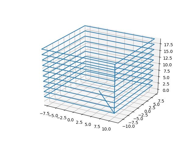
As you can see, however, our slicer is not quite complete. The slicer only prints the edges of an object. Slicers should also add an infill to the inside of the shape in order to build up a real structure.
Adding Infill
Maybe at this point you would like to try to think about how to fill in the slices in a reasonable way? How will you deal with convex as well as concave polygons? What kinds of infill patterns would you write? How could you reuse code between different patterns? Do we have to handle things differently at the tops and bottoms?
Answers
- The answer to the above question is a triangle of base 2 along the x-axis and a height of 2.
- The G-code commands trace a triangle 2 units along the x-axis and with a height of 2, the same as the
.obj.
sliceofpy
I wrote this up into a functional command line slicer called sliceofpy. Find it on GitHub here.